STM32(二)USART串口
- UART (Universal Asynchronous Receiver/Transmitter,通用异步收发器):异步通信,只需要 TX(发送) 和 RX(接收) 两根线。
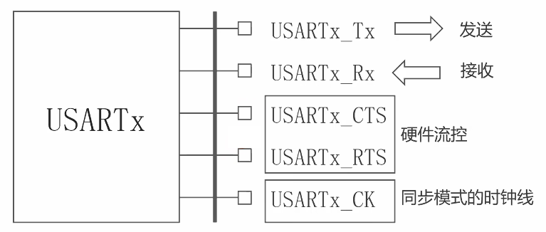
- USART (Universal Synchronous/Asynchronous Receiver/Transmitter,通用同步/异步收发器):同步和异步都支持。它比UART多了一种同步模式。在同步模式下,除了TX、RX,还需要一根时钟线(CK),数据在时钟信号的节拍下传输,速度可以更快,抗干扰能力也更强。
2.1 通信协议
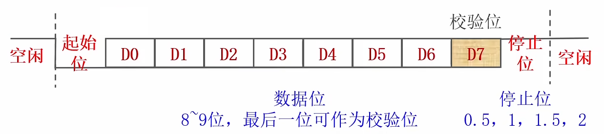
- 空闲时拉高。
- 起始位:1位。空闲时接收到低电平表示起始。
- 数据位:8/9位。从数据的低位开始发送。可以选择是否有校验位。校验位可以选择奇校验还是偶校验(奇校验表示校验数据位1的个数是否为奇数)。
- 停止位:宽度可选。数据位发送完拉高表示停止位。
- 最后如果空闲则拉高,如果还有数据需要发送则再次发送起始位。
2.2 USART
2.2.1 USART模块
下图是USART模块的示意图:
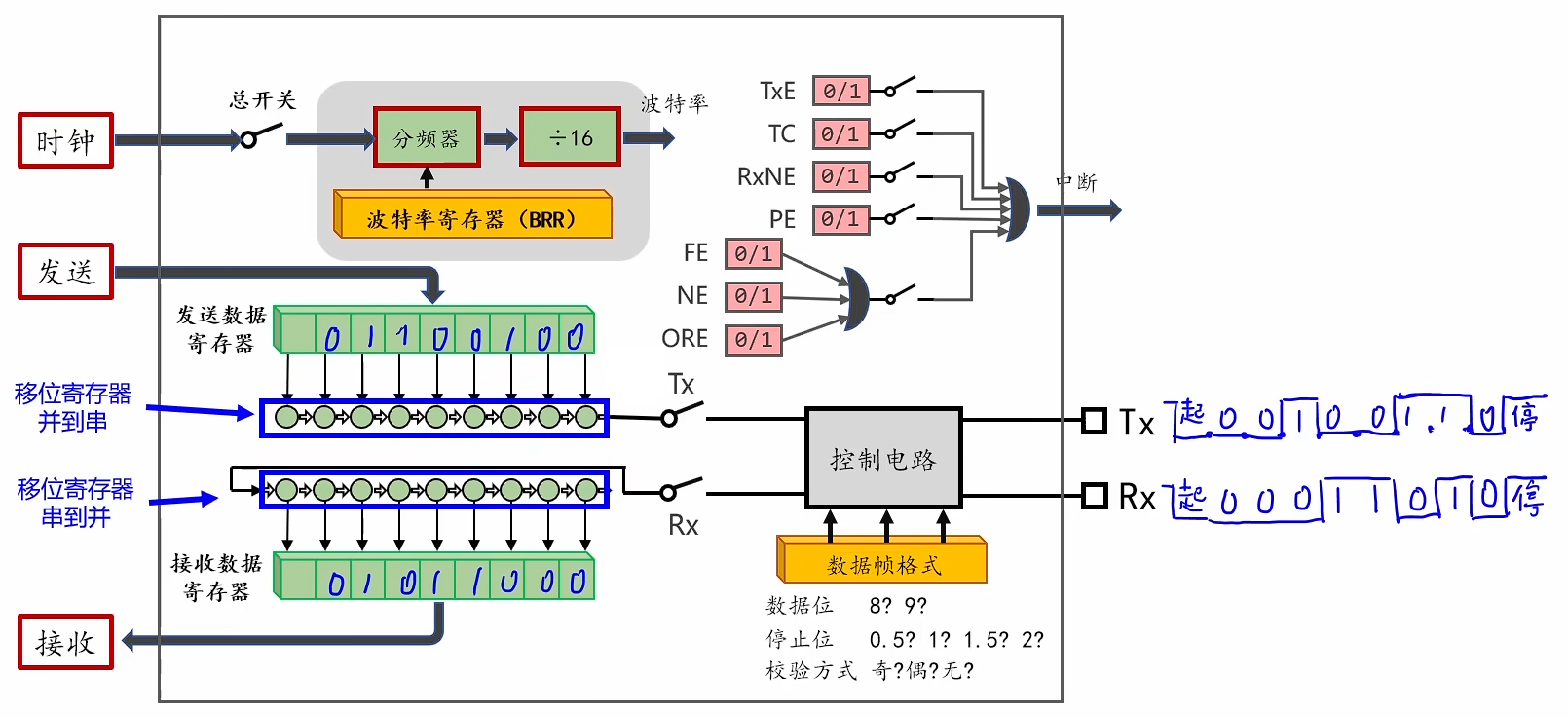
- 发送和接收都有数据寄存器,它们是移位寄存器,用于串并转换。
- 控制电路需要传入数据帧格式。
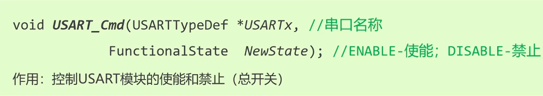
- 左上角有一个总开关,需要使用下面的
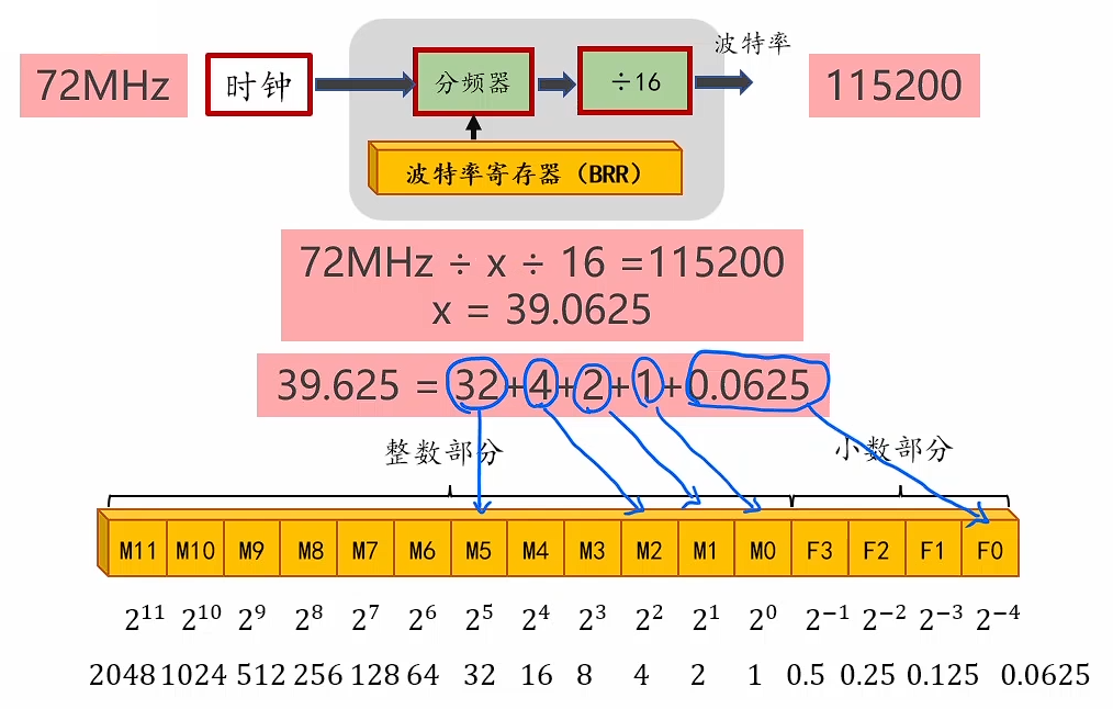
USART_Cmd控制。 - 总开关的右边是时钟分频模块,通过设置波特率寄存器的值可以控制分频器除以几,进而控制输出波特率,计算如下(实际使用时不需要关注这些)。
2.2.2 标志位
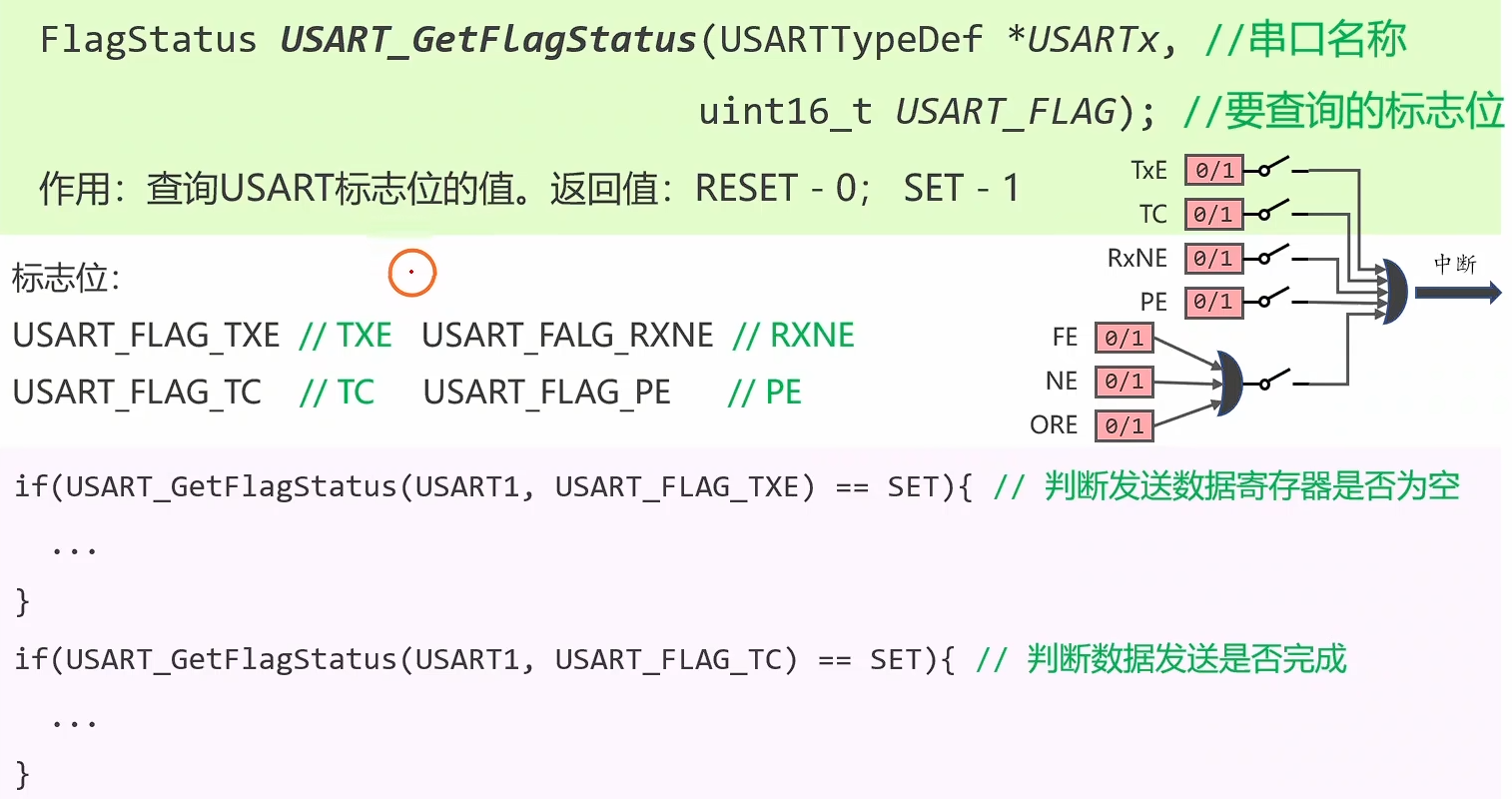
上面的模块示意图右上角有一些标志位:
TxE(Transmit Data Register Empty):表示发送数据寄存器(TDR)是否为空,空则返回1。TC(Transmit Complete):表示发送是否完成,发送数据寄存器和移位寄存器都为空时返回1。RxNE(Receive Data Register Not Empty):表示接收数据寄存器(RDR)是否非空,非空则返回1。PE(Parity Error):奇偶校验错误。FE(Frame Error):帧格式错误,接收到了无效的数据帧(比如没有停止位)。NE(Noise Error):噪声错误,接收的数据中检测到了噪声(比如数据位0的波形中有高电平脉冲)。ORE(Overrun Error):过载错误,由于读接收寄存器太慢导致数据丢失。
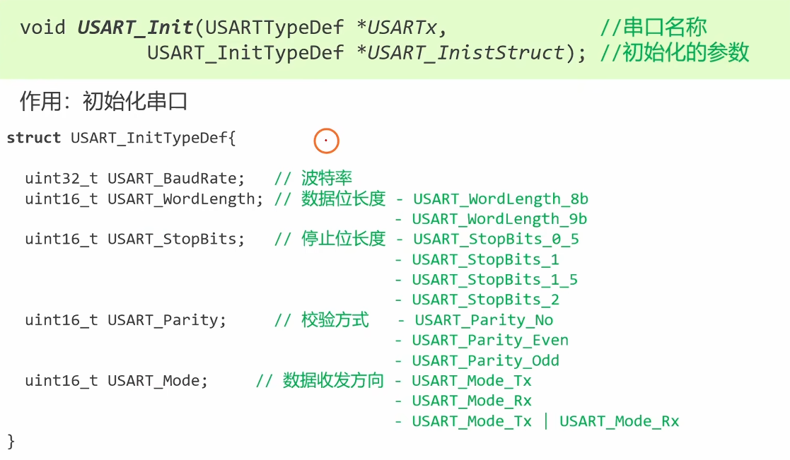
2.2.3 编程接口
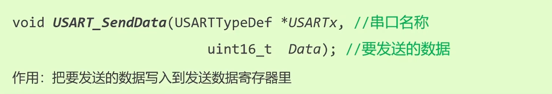
发送的数据可能是9位,因此是
uint16_t类型。
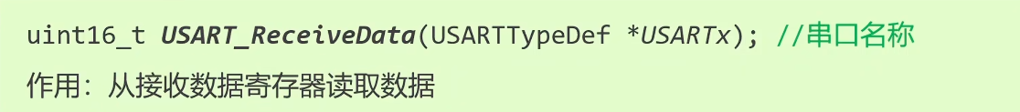
接收数据前,需要等待接收数据寄存器非空。
完整配置代码如下:
RCC_APB2PeriphClockCmd(RCC_APB2Periph_USART1, ENABLE);

USART_InitTypeDef USART_InitStruct;

USART_InitStruct.USART_BaudRate = 115200;
USART_InitStruct.USART_Mode = USART_Mode_Rx | USART_Mode_Tx;
USART_InitStruct.USART_WordLength = USART_WordLength_8b;
USART_InitStruct.USART_StopBits = USART_StopBits_1;
USART_InitStruct.USART_Parity = USART_Parity_No;

USART_Init(USART1, &USART_InitStruct);
USART_Cmd(USART1, ENABLE);
2.3 串口IO引脚
目前只使用TX和RX引脚。
2.3.1 引脚分布表和重映射表
数据手册第3章Table 5有如下表格(节选):
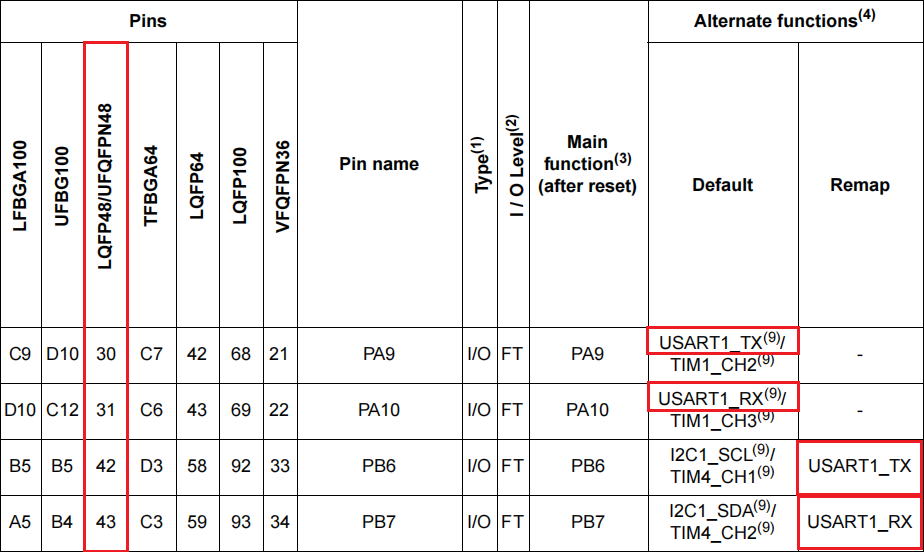
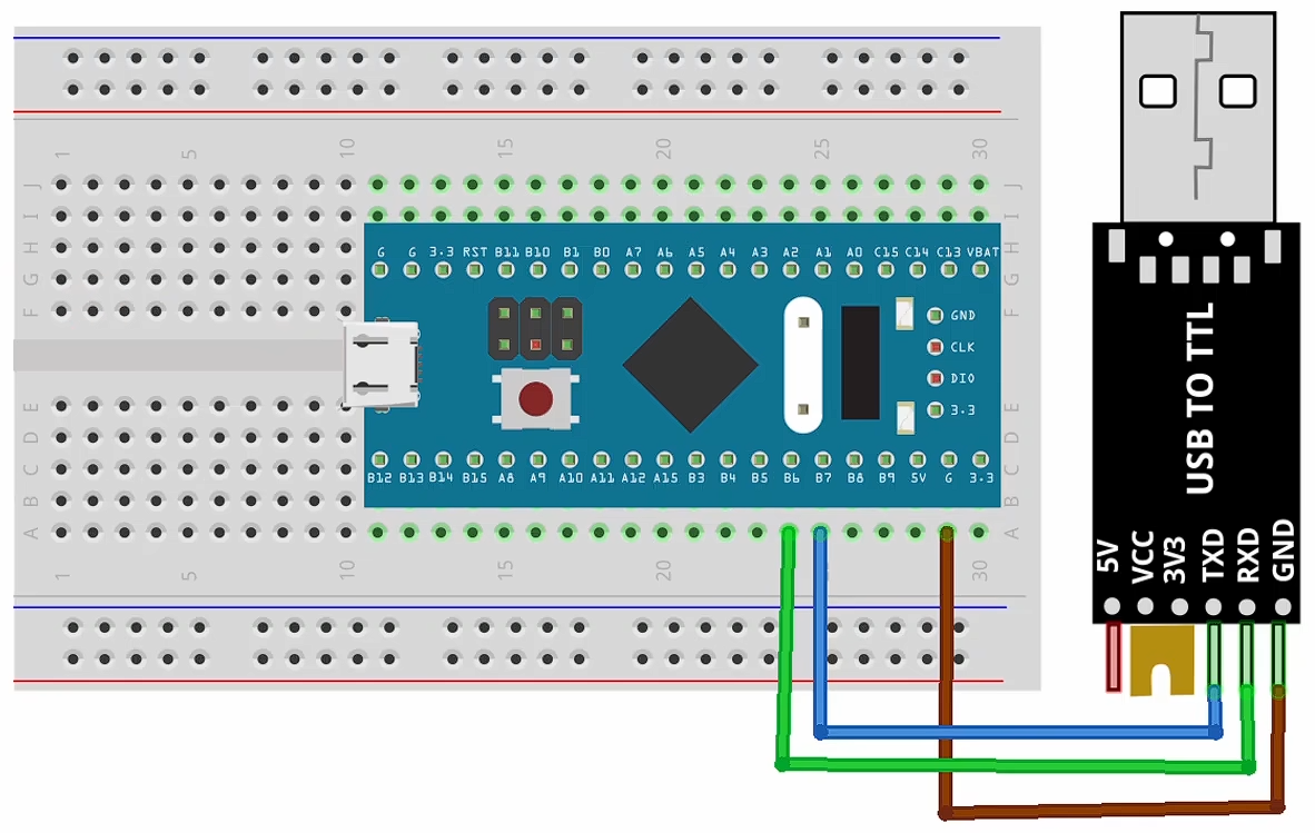
- 默认的TX和RX引脚是
PA9和PA10。 - (如果上面的引脚被占用)重映射后的引脚是
PB6和PB7。
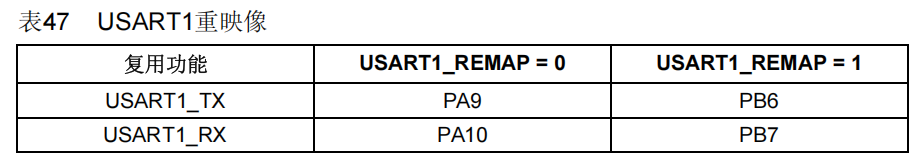
参考手册8.3.8节中也有类似表格:
2.3.2 IO配置表
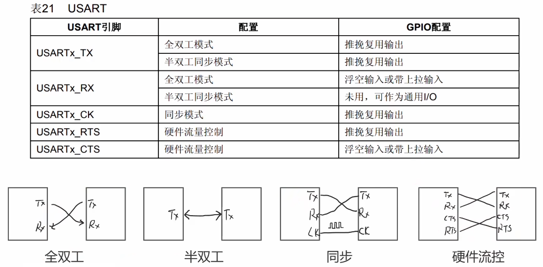
在参考手册8.1.11节中有如下配置表,不同模式参考表格配置即可。
全双工模式下RX推荐选择上拉输入,这样默认高电平,对应空闲时拉高。
2.3.3 代码
- 默认引脚(
PA9、PA10)
RCC_APB2PeriphClockCmd(RCC_APB2Periph_GPIOA, ENABLE);
GPIO_InitTypeDef GPIO_InitStruct;

// Tx PA9 复用输出推挽
GPIO_InitStruct.GPIO_Pin = GPIO_Pin_9;
GPIO_InitStruct.GPIO_Mode = GPIO_Mode_AF_PP;
GPIO_InitStruct.GPIO_Speed = GPIO_Speed_10MHz;
GPIO_Init(GPIOA, &GPIO_InitStruct);

// Rx PA10 输入上拉
GPIO_InitStruct.GPIO_Pin = GPIO_Pin_10;
GPIO_InitStruct.GPIO_Mode = GPIO_Mode_IPU;
GPIO_Init(GPIOA, &GPIO_InitStruct);- 重映射引脚(
PB6、PB7)
// 重映射需要AFIO模块,因此先开启时钟
RCC_APB2PeriphClockCmd(RCC_APB2Periph_AFIO, ENABLE);

// 开启USART重映射(USART1_REMAP = 1)
GPIO_PinRemapConfig(GPIO_Remap_USART1, ENABLE);

RCC_APB2PeriphClockCmd(RCC_APB2Periph_GPIOB, ENABLE);
GPIO_InitTypeDef GPIO_InitStruct;

// Tx PB6 复用输出推挽
GPIO_InitStruct.GPIO_Pin = GPIO_Pin_6;
GPIO_InitStruct.GPIO_Mode = GPIO_Mode_AF_PP;
GPIO_InitStruct.GPIO_Speed = GPIO_Speed_10MHz;
GPIO_Init(GPIOB, &GPIO_InitStruct);

// Rx PB7 输入上拉
GPIO_InitStruct.GPIO_Pin = GPIO_Pin_7;
GPIO_InitStruct.GPIO_Mode = GPIO_Mode_IPU;
GPIO_Init(GPIOB, &GPIO_InitStruct);
2.4 USART实验
2.4.1 发送数据
#include "stm32f10x.h"
#include <stdio.h>

void My_USART_SendBytes(USART_TypeDef* USARTx, uint8_t* pData, uint32_t size) {
    for (uint32_t i = 0; i < size; i++) {
        // 等待发送数据寄存器为空
        while (USART_GetFlagStatus(USARTx, USART_FLAG_TXE) == RESET);
        // 将要发送的数据写入发送数据寄存器
        USART_SendData(USARTx, pData[i]);
    }
    // 等待数据发送完成
    while (USART_GetFlagStatus(USARTx, USART_FLAG_TC) == RESET);
}

void My_USART_Init() {
    // 1. 初始化 IO 引脚
    // 重映射
    RCC_APB2PeriphClockCmd(RCC_APB2Periph_AFIO, ENABLE);
    GPIO_PinRemapConfig(GPIO_Remap_USART1, ENABLE);

    RCC_APB2PeriphClockCmd(RCC_APB2Periph_GPIOB, ENABLE);
    GPIO_InitTypeDef GPIO_InitStruct;

    // Tx PB6 复用输出推挽
    GPIO_InitStruct.GPIO_Pin = GPIO_Pin_6;
    GPIO_InitStruct.GPIO_Mode = GPIO_Mode_AF_PP;
    GPIO_InitStruct.GPIO_Speed = GPIO_Speed_10MHz;
    GPIO_Init(GPIOB, &GPIO_InitStruct);

    // Rx PB7 输入上拉
    GPIO_InitStruct.GPIO_Pin = GPIO_Pin_7;
    GPIO_InitStruct.GPIO_Mode = GPIO_Mode_IPU;
    GPIO_Init(GPIOB, &GPIO_InitStruct);

    // 2. 初始化 USART1
    RCC_APB2PeriphClockCmd(RCC_APB2Periph_USART1, ENABLE);

    USART_InitTypeDef USART_InitStruct;

    USART_InitStruct.USART_BaudRate = 115200;
    USART_InitStruct.USART_Mode = USART_Mode_Rx | USART_Mode_Tx;
    USART_InitStruct.USART_WordLength = USART_WordLength_8b;
    USART_InitStruct.USART_StopBits = USART_StopBits_1;
    USART_InitStruct.USART_Parity = USART_Parity_No;

    USART_Init(USART1, &USART_InitStruct);
    USART_Cmd(USART1, ENABLE);
}

int main(void)
{
    My_USART_Init();

    // 调用自定义函数逐个发送单字节数据
    uint8_t bytes[] = {1, 2, 3, 4, 5};
    My_USART_SendBytes(USART1, bytes, 5);

    // 通过覆盖 fputc 方法,重定向 printf 输出到 USART1
    printf("Hello, USART1!\n");

    while (1) {}
}

// 覆盖 fputc
int fputc(int ch, FILE *f) {
    // 等待发送数据寄存器为空
    while (USART_GetFlagStatus(USART1, USART_FLAG_TXE) == RESET);
    // 发送数据
    USART_SendData(USART1, (uint8_t)ch);
    // 保持原返回值
    return ch;
}
2.4.2 接收数据控制LED
#include "stm32f10x.h"

void My_USART_Init(void);
void My_OnBoardLED_Init(void);

int main(void)
{
    My_USART_Init();
    My_OnBoardLED_Init();

    while (1) {
        // 等待接收数据寄存器非空
        while (USART_GetFlagStatus(USART1, USART_FLAG_RXNE) == RESET);
        // 读取数据
        uint8_t byteRcvd = USART_ReceiveData(USART1);
        // 控制 LED
        if (byteRcvd == '0') {
            GPIO_WriteBit(GPIOC, GPIO_Pin_13, Bit_SET); // 关闭 LED
        } else if (byteRcvd == '1') {
            GPIO_WriteBit(GPIOC, GPIO_Pin_13, Bit_RESET); // 打开 LED
        }
    }
}

// 初始化 USART1
void My_USART_Init(void) {
    // 1. 初始化 IO 引脚
    // 重映射
    RCC_APB2PeriphClockCmd(RCC_APB2Periph_AFIO, ENABLE);
    GPIO_PinRemapConfig(GPIO_Remap_USART1, ENABLE);

    RCC_APB2PeriphClockCmd(RCC_APB2Periph_GPIOB, ENABLE);
    GPIO_InitTypeDef GPIO_InitStruct;

    // Tx PB6 复用输出推挽
    GPIO_InitStruct.GPIO_Pin = GPIO_Pin_6;
    GPIO_InitStruct.GPIO_Mode = GPIO_Mode_AF_PP;
    GPIO_InitStruct.GPIO_Speed = GPIO_Speed_10MHz;
    GPIO_Init(GPIOB, &GPIO_InitStruct);

    // Rx PB7 输入上拉
    GPIO_InitStruct.GPIO_Pin = GPIO_Pin_7;
    GPIO_InitStruct.GPIO_Mode = GPIO_Mode_IPU;
    GPIO_Init(GPIOB, &GPIO_InitStruct);

    // 2. 初始化 USART1
    RCC_APB2PeriphClockCmd(RCC_APB2Periph_USART1, ENABLE);

    USART_InitTypeDef USART_InitStruct;

    USART_InitStruct.USART_BaudRate = 115200;
    USART_InitStruct.USART_Mode = USART_Mode_Rx | USART_Mode_Tx;
    USART_InitStruct.USART_WordLength = USART_WordLength_8b;
    USART_InitStruct.USART_StopBits = USART_StopBits_1;
    USART_InitStruct.USART_Parity = USART_Parity_No;

    USART_Init(USART1, &USART_InitStruct);
    USART_Cmd(USART1, ENABLE);
}

void My_OnBoardLED_Init(void) {
    RCC_APB2PeriphClockCmd(RCC_APB2Periph_GPIOC, ENABLE);
    GPIO_InitTypeDef GPIO_InitStruct;

    // PC13 通用输出开漏
    GPIO_InitStruct.GPIO_Pin = GPIO_Pin_13;
    GPIO_InitStruct.GPIO_Mode = GPIO_Mode_Out_OD;
    GPIO_InitStruct.GPIO_Speed = GPIO_Speed_2MHz;
    GPIO_Init(GPIOC, &GPIO_InitStruct);

    // 默认关闭 LED
    GPIO_WriteBit(GPIOC, GPIO_Pin_13, Bit_SET);
}
2.5 封装函数
在my_lib文件夹下有封装好的USART相关函数,引入头文件就可以使用,包含如下函数:
void My_USART_SendByte(USART_TypeDef *USARTx, const uint8_t Data);
void My_USART_SendBytes(USART_TypeDef *USARTx, const uint8_t *pData, uint16_t Size);
void My_USART_SendChar(USART_TypeDef *USARTx, const char C);
void My_USART_SendString(USART_TypeDef *USARTx, const char *Str);
void My_USART_Printf(USART_TypeDef *USARTx, const char *Format, ...);

uint8_t  My_USART_ReceiveByte(USART_TypeDef *USARTx);
uint16_t My_USART_ReceiveBytes(USART_TypeDef *USARTx, uint8_t *pDataOut, uint16_t Size, int Timeout);
int My_USART_ReceiveLine(USART_TypeDef *USARTx, char *pStrOut, uint16_t MaxLength, uint16_t LineSeperator, int Timeout);STM32(二)USART串口
https://shuusui.site/blog/2026/04/24/hardware/stm32-2/